

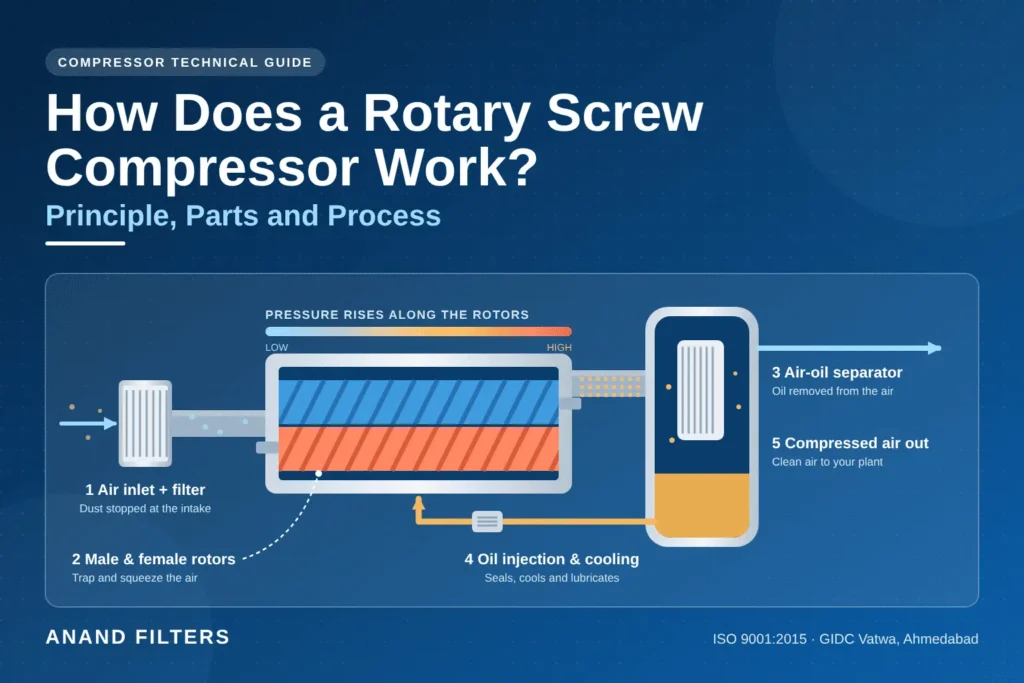
How Does a Rotary Screw Compressor Work? Principle, Parts and Process
Many plant engineers run a screw compressor for years without ever seeing what happens inside it. Yet understanding how a screw compressor works is the quickest way to spot problems early, choose the right filters and oil, and keep your compressed air supply steady. In this guide we explain the principle, the air and oil flow, every major part and the basic care each one needs, in plain language.
Quick answer: a screw compressor works by trapping air between two meshing helical rotors and squeezing it into a smaller space as the rotors turn. In an oil-injected machine, oil seals, cools and lubricates the rotors, and is then separated from the air before the air leaves.
- Air is drawn in through the inlet filter and inlet valve.
- The rotors trap the air and shrink the space around it, raising its pressure.
- The air-oil mixture passes into the separator tank, where the oil drops out.
- The separator element removes the last oil mist, and oil is cooled and filtered for reuse.
- Clean, cooled compressed air flows to the plant.
Table of Contents
- What Is a Rotary Screw Compressor?
- How Does a Rotary Screw Compressor Work? Step by Step
- The Two Flow Paths Inside the Machine
- Screw Compressor Parts and What Each One Does
- Oil-Injected vs Oil-Free Screw Compressors
- How Capacity Control Works
- What Affects Performance in Real Plants
- Advantages and Limits of Screw Compressors
- Basic Maintenance Mapped to Each Part
- Common Problems and the Part Behind Them
- Frequently Asked Questions
- Conclusion
What Is a Rotary Screw Compressor?
A rotary screw compressor, usually just called a screw compressor, is a positive-displacement machine. That means it works by trapping a fixed volume of air and reducing that volume, rather than by speeding the air up like a fan or turbine. The word “rotary” tells you the compressing parts spin continuously, as opposed to a piston that moves back and forth. The word “screw” describes those parts: two interlocking rotors shaped like helical screws.
Because the rotors turn without stopping, the air flow is smooth rather than pulsing, and the machine is built for long running hours. This is why screw compressors are the standard choice for factories, workshops, packaging lines and process plants. There are two main families: oil-injected machines, which are the most common, and oil-free machines, which we compare in a later section. For a wider look at the variations, read our guide to the types of screw compressors.
How Does a Rotary Screw Compressor Work? Step by Step
The screw compressor working principle: two rotors and a shrinking space
At the heart of every machine is the air end, a housing that contains two rotors. The male rotor has rounded lobes, commonly four, and the female rotor has matching grooves, commonly six. The motor drives the male rotor, which in turn drives the female rotor. As they turn, they mesh like a pair of gears, but the gaps between them are carefully shaped so they trap pockets of air.
The four phases of compression
- Intake: as the rotors begin to unmesh at the inlet end, a gap opens and air rushes in through the inlet port.
- Trapping: as rotation continues, the inlet port closes and the air is sealed in a pocket between the rotor lobes and the housing wall.
- Compression: the rotors mesh progressively along their length, so the pocket moves toward the discharge end and gets smaller. The same amount of air in less space means higher pressure.
- Discharge: when the pocket reaches the discharge port, the compressed air is released into the system in a continuous stream.
Because several pockets are always at different stages at the same time, the output is steady. This continuous action is the main practical difference from a piston machine, where air is delivered in separate strokes. If you are comparing the two, our page on reciprocating compressor filters shows how the filtering needs differ.
Why oil is injected into the compression chamber
In an oil-injected screw compressor, oil is sprayed into the air end during compression. It does three jobs at once:
- Seals: it fills the tiny clearances between the rotors and the housing, which stops compressed air leaking back.
- Cools: it absorbs most of the heat created by compression, so the air end stays within a safe temperature.
- Lubricates: it protects the rotors and bearings from wear.
Choosing the right oil matters. Our guides on which oil is used in screw compressors and how to choose the right screw compressor oil explain the options.
The Two Flow Paths Inside the Machine
The easiest way to understand an oil-injected machine is to follow two loops at the same time: the air path, which ends at your plant, and the oil path, which stays inside the compressor and keeps recycling.
Air path
Oil path
The air path
Air first passes through the inlet filter, which removes dust, and then through the inlet valve, which controls how much air enters. The rotors compress it, and the hot air-oil mixture leaves the air end and enters the separator tank. There, the change in direction and drop in speed make most of the oil fall out. The remaining oil mist is caught by the separator element, so the air leaving the tank carries only a few parts per million of oil when the element is healthy.
The air then reaches the minimum pressure valve, which stays closed until the tank has built up a set pressure. It is often in the region of 4 to 5 bar, though the exact setting depends on the model. This ensures oil circulates properly during start-up and also stops system air flowing backward. Next, the aftercooler cools the air, which makes water vapour condense, and the moisture separator removes that liquid. The air is then ready for a receiver, dryer or the plant line.
The oil path
Oil collects in the lower part of the separator tank. In many designs, the pressure in the tank itself pushes the oil around the circuit, so no separate oil pump is needed. A thermostatic valve decides where the oil goes: when the oil is cold, it bypasses the cooler so the machine warms up quickly; when hot, it is sent through the oil cooler. The oil then passes through the oil filter, which removes wear particles, before being injected into the air end and bearings again. A scavenge line also returns the oil collected at the bottom of the separator element back to the air end. For more on the separation stage, read our guide to air-oil separator working principles.
Screw Compressor Parts and What Each One Does
Knowing the main screw compressor parts, and the warning signs for each, makes service planning much easier. The table below summarises them in the order air and oil meet them.
| Part | What it does | Sign of trouble |
|---|---|---|
| Air filter | Removes dust from the intake air before it reaches the rotors | Lower air output, higher power draw, restriction indicator on |
| Inlet (suction) valve | Opens and closes to control air entering the air end | Slow loading, air leaking while unloaded, pressure swings |
| Air end (rotors, bearings, housing) | Compresses the air | Unusual noise, high discharge temperature, falling output |
| Motor and coupling | Drive the male rotor | Vibration, overheating, high current draw |
| Separator tank | Holds the oil and removes most of it from the air | Oil level swings, oil leaks, safety valve opening |
| Air-oil separator element | Removes fine oil mist from the compressed air | Oil in the air line, high differential pressure |
| Oil filter | Removes wear particles and sludge from the oil | Rising oil temperature, low oil pressure |
| Oil cooler and thermostatic valve | Control oil temperature | High oil or discharge temperature, condensation in cold oil |
| Minimum pressure valve | Builds tank pressure for oil flow and prevents backflow | Slow pressure build-up, oil starvation at start-up |
| Check valve and blow-down valve | Stop reverse flow, and release tank pressure when the compressor unloads or stops | Hard starts, air or oil blowing back at shutdown |
| Aftercooler and moisture separator | Cool the air and remove condensed water | Wet air downstream, blocked drain |
| Safety relief valve | Protects the system from over-pressure | Frequent venting, which signals a control or separator problem |
| Controller and sensors | Monitor pressure and temperature and control loading | False alarms, erratic loading |
Three of these parts are consumables that wear out in normal use: the air filter, the oil filter and the separator element. You can browse our compressor air filters, air-oil separators and spin-on separators to see the elements involved, or read about the types of compressor filters for a deeper comparison. When you buy replacements, use our genuine screw compressor spares buyer’s checklist to avoid poor-quality parts.
Oil-Injected vs Oil-Free Screw Compressors
Not every rotary screw compressor uses oil in the compression chamber. Oil-free machines keep the rotors from touching by using timing gears, so no oil is needed to seal or lubricate the compression space. The table below compares the two designs in general terms.
| Feature | Oil-injected | Oil-free |
|---|---|---|
| Sealing and cooling | Oil seals, cools and lubricates the rotors | Close rotor clearances and timing gears, with external cooling |
| Air purity | Needs a separator stage; a small amount of oil can remain | No oil in the compression chamber |
| Typical stages | Often one stage reaches working pressure | Often two stages with an intercooler between them |
| Energy efficiency | Generally higher | Generally lower |
| Purchase cost | Generally lower | Generally higher |
| Typical uses | General manufacturing, workshops, packaging | Food, pharma, electronics and other oil-sensitive processes |
Which one is right depends on how clean your air must be. Our comparison of oil-free vs oil-injected screw compressors explains how the separator and filter technology differs, and our pages on filters for pharma and biotech and filters for dairy, food and beverages show industries where air purity is critical.
How Capacity Control Works
Plant demand for air rises and falls, but the compressor cannot simply switch off and on without penalty. Capacity control matches the compressor’s output to demand. The three common methods are:
| Method | How it works | Best suited to | Limitation |
|---|---|---|---|
| Load/unload | At the upper pressure the inlet valve closes and the tank is vented, so the rotors spin without compressing. At the lower pressure the compressor loads again. | Fairly steady demand | Unloaded running still uses some power |
| Modulation | The inlet valve closes gradually as pressure rises, which reduces the amount of air entering. | Demand that changes slowly within a narrow range | Efficiency drops at lower loads |
| Variable speed drive | The motor speed changes to match demand, so output follows the plant’s needs. | Fluctuating demand | Higher purchase cost and added electronics |
Whichever method is used, the inlet valve, blow-down valve and controller work together, which is why those parts appear in the table above. If you are still deciding what size and type of machine you need, read how to choose the right compressor for your needs.
What Affects Performance in Real Plants
Discharge pressure
Industrial machines commonly deliver compressed air in the range of roughly 7 to 13 bar, but always confirm the rated pressure on your model’s nameplate. Running at a higher pressure than the process needs wastes energy, so set the pressure no higher than required.
Cooling method and ambient conditions
Air-cooled machines use fans to push ambient air across the coolers, so hot, dusty or humid conditions reduce cooling performance and clog the cooler fins. Water-cooled machines use a cooling-water circuit, which suits hot environments but needs clean, treated water. In India’s summer heat and during the monsoon, keep the compressor room ventilated and the coolers clean.
Pressure drop from clogged consumables
A loaded air filter or separator element adds resistance. The machine then works harder for the same output, which raises energy use and heat. Read how compressor filters improve air quality and equipment lifespan for more on this effect.
Advantages and Limits of Screw Compressors
- Continuous duty: built to run for long hours without the pauses a small piston machine needs.
- Smooth, steady air: little pulsation, so the air supply is stable.
- Compact and quiet: less vibration than many piston machines of similar output.
- Dependent on clean consumables: poor filters or oil shorten air end life and raise running cost.
- Higher purchase cost for small, occasional use: a small piston unit can be more economical when demand is low and intermittent.
Basic Maintenance Mapped to Each Part
Safety first: before any inspection or part change, stop the compressor, isolate and lock out the power, and let the system depressurise fully, including the separator tank. Never open a housing that may still be under pressure, and follow your manufacturer’s service manual.
| Part | What to check | When to act |
|---|---|---|
| Air filter | Restriction indicator, visible dirt on the element | Indicator is on, output drops or the site is dusty |
| Oil and oil filter | Oil level, colour, temperature, filter condition | At each scheduled oil service, or sooner if oil darkens |
| Separator element | Differential pressure, oil carryover | Pressure difference rises or oil appears downstream |
| Coolers | Dust build-up, leaks, oil and discharge temperature | Temperature rises above normal |
| Drain and moisture separator | Condensate discharge | Water appears in the line or the drain is blocked |
Replacement intervals depend on your model, oil grade and site conditions, so take them from the service manual. For practical guidance, read our articles on air compressor air filter replacement signs, the air-oil separator filter replacement guide, how to know when your industrial air compressor needs servicing and why regularly replacing filters in compressors matters.
Common Problems and the Part Behind Them
| Symptom | Parts to check first |
|---|---|
| Low air output or pressure | Air filter, inlet valve, separator element, air leaks |
| Overheating | Oil level, oil filter, oil cooler, thermostatic valve, ambient airflow |
| Oil in the air line | Separator element, scavenge line |
| High oil consumption | Separator element, oil leaks, over-filled tank |
| Unusual noise or vibration | Bearings, coupling, air end; call a service engineer promptly |
Oil carryover is the most common cause of concern for air quality. Our guides on oil separator failure symptoms and choosing the right air-oil separator explain how to diagnose and fix it.
Frequently Asked Questions
How does a screw compressor work?
A screw compressor traps air between two meshing helical rotors. As the rotors turn, the trapped space shrinks, raising the air’s pressure. The compressed air then passes through separation and cooling stages before leaving the machine.
What is the working principle of a rotary screw compressor?
It is a positive-displacement principle. Air is trapped in pockets between rotating male and female rotors, and the pocket volume reduces as the rotors mesh, which increases the pressure continuously.
What are the main parts of a screw compressor?
The main parts are the air filter, inlet valve, air end with rotors, motor, separator tank and element, oil filter, oil cooler, minimum pressure valve, aftercooler and controller.
Why is oil injected into a screw compressor?
Oil seals the gaps between the rotors, absorbs the heat of compression and lubricates the rotors and bearings. It is separated from the air afterwards and reused.
What is the difference between oil-injected and oil-free screw compressors?
Oil-injected machines use oil in the compression chamber and are generally more efficient. Oil-free machines keep oil out of the chamber and suit oil-sensitive processes, but usually cost more and use more energy.
What does the minimum pressure valve do?
It stays closed until the separator tank reaches a set pressure, which ensures oil circulates correctly at start-up. It also stops compressed air from flowing back into the machine.
How is a screw compressor different from a piston compressor?
A screw compressor uses rotating rotors for smooth, continuous flow and long running hours. A piston compressor uses a back-and-forth piston, delivers air in pulses and suits smaller, intermittent duty.
Conclusion
How a screw compressor works comes down to two ideas: two meshing rotors that squeeze trapped air into a smaller space, and two loops that support them. The air loop cleans and cools the air for your plant, and the oil loop seals, cools and lubricates the rotors, then returns to the air end. Once you know the parts and their warning signs, it becomes much easier to plan maintenance, pick the right consumables and prevent unplanned stops.
Anand Filters: Industrial Filter Manufacturers supplies compressor air filters, air-oil separators and related elements. Learn more about us or explore our services.
Need the right filters or separators for your compressor? Share your compressor model and running hours, and our team will help you choose the correct element. Browse our compressor filter range or contact us for a quotation.